Modern Robotics Motor Controller Fix
By Erik Badger
February 18 2016, 8:24pm
UNFORTUNATELY ALL OF THE CHANGES IN THIS POST ARE ILLEGAL SO YOU WONT BE ABLE TO USE THIS IN COMPETITION BUT IT IS A INTERESTING PROOF OF CONCEPT.
Materials : 4 0.1 uF capacitors ($0.07); Solder; Soldering iron;
Estimated Time Per Module : 10 Minutes (First may be longer)
Procedure:
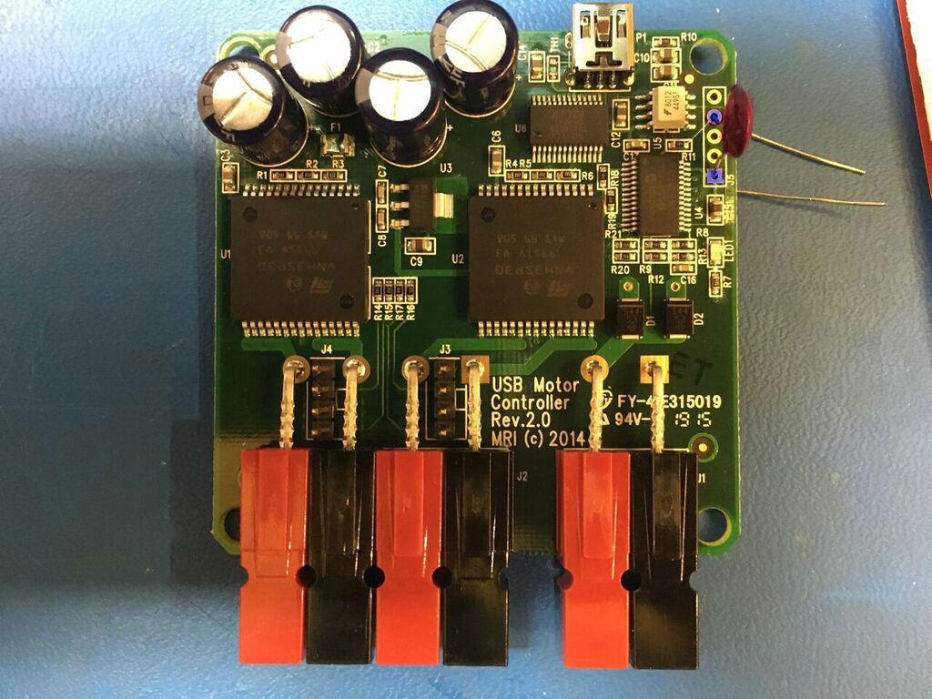
We need to put a 0.1 uF capacitor between the ground and MCLR pin. Conveniently those two pins are connected to the programming pins 1 and 4. Pin 1 is the is the pine which is slightly filled in and you count away from that.
You may want to test each module before you move on to the next. I recommend making a program that will run the motors to make sure you haven't shorted anything out.
Steps:
1. Place one capacitor tail into pin 1
2. solder tail into pin making sure the capacitor is inline with the pins.
3. place second tail of capacitor into pin 4
4. solder tail into pin
5. test motor controller(run motor in both directions)
The capacitor(which is highlighted red) is going into programming pin 1 and 4 (highlighted blue)
